
A mold crack should not be covered with filler wire and returned to production. The crack must be traced to its full extent, contaminated or fatigued steel must be removed, and the prepared groove must be fused from the root outward.
Laser welding suits many localized cracks because it allows controlled filler deposition with limited heat input. Structural failures require separate evaluation. Cracks through a major load-bearing section, repeatedly failed repairs, lost datums, or a compromised mold base require an engineering review to decide whether a damaged mold should be repaired or replaced before welding begins.
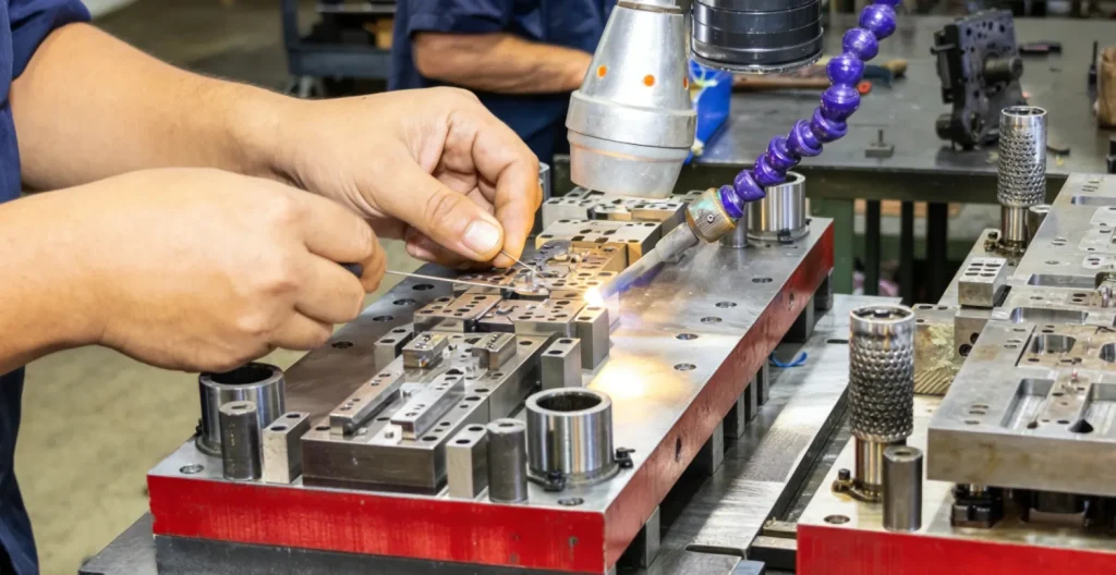
Determine Whether the Crack Is Repairable
Record:
- Crack location, length, direction, and visible opening
- Steel grade, hardness, and heat-treatment condition
- Mold function and stress at the damaged area
- Shot count, thermal history, and previous repairs
- Whether the crack reaches a water line, fastener, insert seat, corner, or structural section
- Required post-repair tolerance, polish, or texture
Use a suitable inspection method to identify the crack boundary. If penetrant testing is used, all penetrant residue must be completely removed before welding. A visible surface line may extend deeper than expected, so inspect again after preparation.
Why Use a Rounded U-Groove?
A narrow V-groove can be difficult to clean and fuse at the root. A smooth U-shaped preparation gives the laser and filler better access to the bottom and sidewalls.
Use a ball-nose burr or another controlled method to remove the crack and fatigued material. Continue until inspection shows no remaining crack indication. Do not make the groove wider or deeper than necessary, but do not leave a hidden crack to save preparation time.
Step-by-Step Crack Repair Workflow
1. Remove contamination
Clean oil, grease, release agent, corrosion, penetrant residue, and grinding debris from the crack and surrounding area. Use a method compatible with the mold surface and workshop safety procedure.
2. Confirm the prepared groove
Inspect the root and sidewalls under magnification. The groove should be smooth, accessible, and free of sharp trapped corners or remaining crack indications.
3. Establish settings on representative material
Use matching scrap or a non-critical area where practical. Confirm spot size, pulse width, frequency, peak energy, shielding, and wire behavior before welding the production tool.
4. Fuse the root
Use a controlled initial pass to confirm clean fusion at the bottom of the groove. Add filler only when the root condition and settings are stable.
5. Build the sidewalls and center
For a wider groove, deposit along the sidewalls before filling the center. Maintain consistent overlap and verify that each layer fuses with the previous deposit. Avoid trapping porosity between layers.

6. Fill in thin layers
Build the repair progressively rather than trying to fill the full depth in one pass. Manage heat accumulation and allow controlled cooling between sequences where required by the material and mold mass.
7. Apply a controlled cap
Leave only the finishing allowance needed for machining, grinding, stoning, or polishing. Excessive overbuild adds heat and unnecessary finishing work.
8. Finish and inspect
Restore the required geometry and surface finish. Inspect the repaired area for cracking, lack of fusion, porosity, sink, and dimensional change. Recheck after finishing because machining can expose hidden defects.
Recommended Laser Welding Parameters for Mold Crack Repair
The following values are conservative starting windows, not universal production settings. Actual settings depend on the laser source, optics, spot size, wire, steel grade, hardness, groove depth, and machine response.
| Item | Typical starting window | Adjustment objective |
| Pulse width | Approximately 3–8 ms | Balance fusion with heat input; longer is not automatically better |
| Frequency | Approximately 4–8 Hz | Control deposition rate and heat accumulation |
| Spot size | Approximately 0.4–1.0 mm | Match the prepared groove and filler-wire diameter |
| Pulse overlap | Consistent overlapping spots | Avoid gaps while limiting unnecessary reheating |
| Shielding gas | Stable argon flow suitable for the head and repair area | Protect the weld pool without turbulence |
For H13, S7, and other crack-sensitive steels, preheat, interpass temperature, pulse shaping, filler selection, and post-treatment must be decided from the material condition and repair procedure. Do not apply a universal “no preheat” rule.
Filler Wire Selection
Match the filler to the base-steel chemistry, hardness, repair depth, and final surface requirement. A wire that is acceptable for P20 may not polish, texture, or respond correctly on NAK80, H13, S7, or stainless mold steel.
Deep repairs sometimes require a planned buffer and cap strategy, but the exact alloy combination should be approved for the tool rather than copied from a generic chart. Start by checking how to match welding wire to mold steel, then validate the proposed combination on representative material where practical.

Troubleshooting Common Crack-Repair Defects
| Problem | Likely cause | Corrective direction |
| Porosity | Oil, penetrant, oxide, unstable shielding, or contamination between layers | Stop, remove the defective material, clean again, stabilize shielding, and rebuild from sound metal |
| Crack returns beside the weld | Original crack not fully removed, filler mismatch, excessive hardness, high restraint, or uncontrolled cooling | Reinspect the full crack, revise preparation and material procedure, and address the original stress source |
| Lack of fusion at the sidewall | Groove too narrow, poor access, incorrect spot placement, or excessive filler | Reprepare the area and rebuild with controlled sidewall fusion |
| Sink or distortion | Excessive accumulated heat or overbuilding | Reduce average heat input, shorten sequences, allow controlled cooling, and deposit only the required amount |
| Poor polish or visible halo | Incompatible filler, porosity, hardness mismatch, or incorrect finishing | Recheck wire selection and test the full weld-and-finish process on representative material |
Keep Crack Repair Separate From Other Mold Topics
- Worn sealing edges, corners, shut-offs, and flash require an edge-geometry workflow rather than crack excavation and root filling.
- For a broader view of defect types, method selection, and process boundaries, review mold and die laser repair applications before applying this crack-specific workflow.
- Compare equipment only after the crack geometry, mold access, material condition, filler strategy, and finishing requirement have been defined.
Safety Note
Laser welding equipment requires controls appropriate to its laser class and wavelength, including a controlled work area, guarding or enclosure, interlocks where applicable, fume extraction, and wavelength-rated eye protection. Follow the machine manufacturer’s instructions and the site’s approved laser-safety procedure.
Send the crack location, mold material, hardness, depth, previous repair history, photos, and required finish. Riselaser can review the repair approach and recommend a suitable test-weld plan or machine configuration.
Request a Mold Crack Review →


